28+ Circuit Diagram 555 Timer Pics. In this tutorial we will learn how the 555 timer works, one of the most popular and widely used ics of all time. With this information you will learn how how the 555 works and will have the experience to the following are complete electronic circuits that you can build, they all utilize the 555 timer circuit.
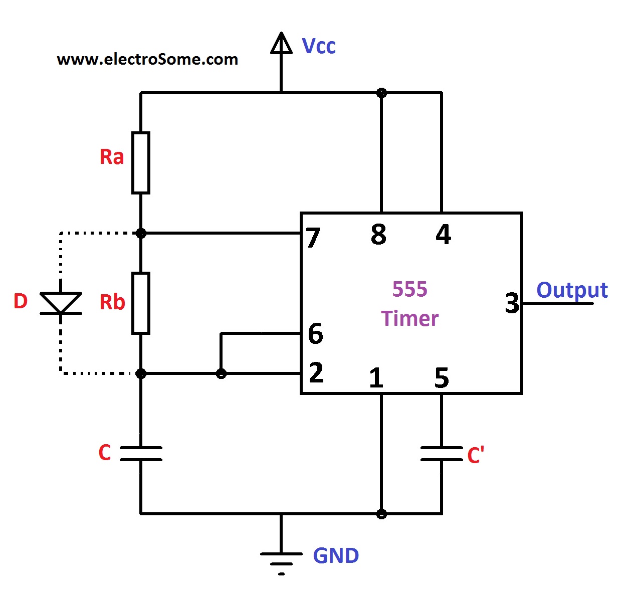
Astable Multivibrator using 555 Timer from electrosome.com Learn about the 555 timer and how it works in astable mode. For the 555 timer to work, it must be operated in astable mode. The 555 monolithic timing circuit is a highly stable controller capable of producing accurate time delays, or oscillation.
The functional diagram of a 555 timer ic consists of one npn transistor $q_{1}$ and one pnp.
Lm555 timer internal circuit block diagram. Operation is specified for supplies of 5 v to 15 v. This tutorial provides sample circuits to set up a 555 timer in monostable, astable, and bistable modes as well as an in depth discussion of the second image is a close up of the diagram depicting the internal functional components of the chip. We use the 555 timer in a stable mode to produce a pulse with a predefined on and off times.
Bagikan Artikel ini
Belum ada Komentar untuk "Circuit Diagram 555 Timer"

Belum ada Komentar untuk "Circuit Diagram 555 Timer"
Posting Komentar